Fluorine Notes, 2010, 72, 1-2
PECULIARITIES OF TETRAFLUOROETHYLENE DIRECT FLUORINATION IN SOLID AND LIQUID PERFLUOROORGANIC MEDIA
S. R. Allayarov1, I.P. Kim1, I.M. Barkalov1, A.A. Karnauch1, I.V. Markin2, D.A.Dixon.3
1) Institute of Problems of Chemical Physics RAS, Chernogolovka, Russia.
2) FSU Russian scientific centre "Applied Chemistry", Perm Affiliate, Perm, Russia.
3)Chemical Department of Alabama University, Tuscaloosa, USA
Abstract:
The feasibility of tetrafluoroethylene (TFE) safe fluorination
in solid and liquid perfluoroorganic media was considered. The process was controlled by
the methods of low-temperature calorimetry and EPR-spectroscopy. The analysis of the working
mixture was carried out prior and after the experiments.
In the absence of diluents
the fluorination of TFE and hexafluoropropylene (HFP) crystal samples requires arduous explosive
operational conditions. HFP oligomers: dimer (HFP)2 and trimer (HFP)3 were applied for diluents in TFE solid-phase mixtures fluorination. The required regime was
shown to soften when passing from TFE to [TFE-(HFP)2] and to [TFE-(HFP)3].
If the latter is the case, the process starts when the mixture converts from glass to supercooled
liquid.
Linear and branched perfluoroalkanes, perfluoroaromatic substances, (HFP)2,
(HFP)3, and mixtures thereof were tested for TFE diluents in liquid systems. It
was shown that for the systems with HFP oligomers there is a threshold value (for temperature,
fluorine content, process depth) for comparably soft process behaviour with selective formation
of C2F6. The arduous regime proved to be the only possible for those systems above the said
threshold and for all other systems in all cases; besides of strong heating, high yield of
products resulting from C=C bond (in TFE) breaking, and diluents consumption the regime tends
to exhibit flashes and explosions. The mechanism proposed for TFE fluorination in condensed
media is based on the idea of excited products formation due to exothermal elementary acts
and their impact on the process kinetics. Specifically, a conclusion is made about the stabilization
of fluorine/TFE/med2ium complexes at the phase change-over points for the system
components that participate at higher temperatures in the generation of radicals, including
those long-lived. Their role in the process of perfluoroolefin fluorination is discussed.
Key words: tetrafluoroethylene, hexafluoropropylene, direct fluorination, perfluoroorganic condensed media, reaction mechanism, long-lived perfluororadicals
Introduction
Fluorination of organic substances by molecular fluorine is a widely applied method for the modification of physical and chemical properties of polymers and for the manufacture of polymers or low-molecular substances [1-13].
The singularity of TFE reaction with elemental fluorine is due to high activity of both molecules in radical reactions that determine promising outlooks for the system application in handling of many practical and scientific problems. When exposed to the action of fluorine TFE ¦Р-bond is strongly polarized due to positive mesomeric effect of fluorines in molecular fluorine, and TFE therefore obtains some bi-radical features. This is the reason for the sensitivity of fluorine-activated TFE to the presence of radicals in general [14], and particularly for its activity in radical-chain polymerization [15]. Yet, in practice, direct fluorination of organics in various phases is widely known for unpredictable effects of the reaction medium overheating. The reaction of fluorine with most of organic substances is highly exothermic due to the formation of C-F bonds, and may be followed by combustion and explosions. For better safety the process may be conducted under the conditions of considerable thinning with inert diluents.
TFE in-liquid fluorination may occur either on liquid-gas interfaces or in gas bubbles, and, being not entirely homogenous the process is regarded as a dangerous one. Nevertheless, the investigation of in-liquid fluorination were pioneered and developed by Merritt et al. [16, 17] who were the first to prove the possibility of fluorine addition to olefins of specific types. However, unlike direct chlorination or bromination of olefins the production of 1,2-difluoro-derivatives through the addition of fluorine by the olefin double bond was considered as a difficult issue, and some bypassing approaches were being developed to avoid the use of fluorine [9, 18, 19]. Thus, in [13] it was proposed to apply (HFP)3 for an effective medium for in-liquid fluorination of unsaturated perfluorinated substances with elemental fluorine, and when so doing they did not reveal any traces of by-products due to side-reactions of polymerization or destruction (with explosion) of the original monomer that attend this process usually.
The addition of fluorine to undiluted perfluoroolefins was studied in gaseous and liquid phases [12, 13, 20-23]. In the absence of strong heating or explosions perfluoroalkanes were proved to be the main reaction products. However, neither the mechanism of those products formation nor the impact of heating was investigated. Yet it is necessary to understand the said mechanism in order to substantiate the choice of the method for the manufacture of perfluoroorganic substances via direct fluorination.
The novel step in the research of direct fluorination of perfluoroolefins started after the discovery of long-lived perfluoroalkyl radicals (LR) during in-liquid fluorination of (HFP)3 [21]. Basing on [20-22, 24-28,] in [24] the conclusion was made about the formation of LRs thanks to fluorine adding to the double bond of perfluoroolefins in this case those were HFP oligomers. The study of fluorocarbon radicals by the method of in-liquid EPR-spectroscopy seem to have some benefits [27]. Free rotation of radicals in liquid averages the anisotropy of superfine interaction. Then the width of superfine structure components in EPR-spectrum decreases and both the intensity of those components and the distance between them are measurable with high accuracy. It is then rendered possible to accumulate in liquid high LR concentrations for comprehensive study. It is possible correspondingly to reveal the specific features of HFP oligomer fluorination and the role of LR in the process. The fact that LRs are formed during the direct fluorination of HFP oligomers evidences the prevailing of chain mechanism among all other possible processes of non-saturated bonds fluorination [24].
In this our study we investigated in details the peculiarities of TFE fluorination in liquid mixtures with various perfluoroorganic substances, and in glassy mixtures with HFP oligomers only. The main objective of the study was to determine the conditions for the safe process realization that would allow correct interpretation of the observed regularities. It might provide the basis for the further progress in the understanding of the detailed mechanisms for the mentioned processes.
Experimental Techniques
The characteristics of fluoroorganic substances used in this study are presented in Table 1. All those substances and F2 were manufactured by FSUE RSC "Applied Chemistry" (Perm Affiliate).
The fluorination of liquid TFE/diluents mixtures and that of pure diluents was carried out in various reactors that differ by the method of organic components, mixtures and fluorine delivery, and by the accident control measures.
The fluorination of diluents like (HFP)3 oligomer notable for its low reactivity was carried out in a stainless steel reactor provided with a blender and systems for the delivery of fluorine and for the sampling of gaseous products. Fluorine under initial surplus pressure (0.3 - 0.7MPA) was delivered into the reactor with liquid perfluoroolefin and the reaction was stopped when the said surplus pressure dropped to 0.01 MPa. The rate of fluorine delivery into the reactor was about 25 l/h. The initial temperature ranged between 263 K and 343 K.
For the fluorination of TFE mixed with liquid fluoroorganic substances we used a stainless reactor ( volume 5,5 dm3) equipped with two siphons for gas delivery (F2 and TFE bubbling), manometer for each gas pressure measurement, thermocouple and turbine stirrer (n = 300 rpm). The gas reagent mole ratio variation ¦Б = F2: TFE (1,05-1,2) was provided by their rate adjustment from 25 l/h (1,115 mole/h) to 26,2 l/h (1,17mole/h). The initial reactor temperature varied from 203 to 283K. Reducing the risk of the reaction withdrawal into the reactor free volume above the liquid (sometimes with the explosion) was achieved by filling the volume with passivated copper shavings.
Both phase transitions and the kinetics of TFE fluorination in glassy solutions of HFP oligomers were studied by the method of low-temperature calorimetry [29] using special quartz cells. The designed sample of perfluoroolefin was placed into a quartz cell and evacuated to residual pressure 0.13 Pa at 77 K, after that designed quantity of fluorine gas was added into it. The ampoule thus prepared was put into a calorimeter, where all possible heat effects were traced during its unfreezing.
The dynamics of the paramagnetic centres formation was measured with the help of EPR spectrometry. A sample of perfluoroorganics or perfluoroolefin was charged into a quartz EPR ampoule (4-5mm in diameter) and degassed at 77 K to 10-3 mm then fluorine gas was admitted into the ampoule. The measurement error for the absolute concentration of paramagnetic centres was (20-30)%, while that for the relative concentration was (5-10)%. The samples heating was conducted with the help of nitrogen vapour stream, those samples were kept at each experimental temperature for 8-10 min. EPR spectra were recorded at 77 K with the help of a desk-size radiospectrometer PS100.X with automatic treatment of EPR spectra. Automatic record was conducted with the help of EPRWIN software. Theoretical processing and spectra simulation were made using EPRTOOLS software. Both EPRWIN and EPRTOOLS were produced by NPP "Adany" (Minsk, Belarus).
Chromatographic analysis of gaseous and liquid products was carried out with the help of LHM instrument. For sorbent we applied Al2O3-supported (25:100) dibutylphtalate/vaseline oil blend (1:1). The column length was 5 m, its diameter was 3 mm. Detector current was 130 mA. The gas-carrier (argon) flow in gas analysis was 1.0 l/h, and in liquid phase analysis it was 4.91 l/h.
RESULTS AND DISCUSSION
I. Fluorination of TFE in solid-phase perfluoroorganic (PFO) media
TFE to fluorine reactivity in solid phase is estimated from the results of experiment sequences conducted in the systems of individual TFE and HFP fluorination and in glassy mixtures of TFE with HFP dimers and trimers. For those last-named their phase transformations and reactivity to fluorine within corresponding temperature ranges were also considered. All this may provide additional data on the mechanism of LR generation and their participation in TFE fluorination process.
A). TFE and HFP fluorination in crystal state
In Fig.1,1-1' and 1,2-2' the calorimetric curves are presented related to unfreezing of TFE and HFP samples cooled to 77K, correspondingly, making it possible to compare phase states and reactivity relative to fluorine of the most simple perfluoroolefins at sufficiently low temperature.
The calorimetric curve for unfreezing of TFE sample cooled to 77 K is shown in Fig. 1,1. The endothermic peak for TFE crystal melting (142K) is registered during its heating to room temperature.
Fig.1. Calorimetric curves for the unfreezing of TFE (1) and HFP (2), and for TFE:F2=99:1 mole% (1') and HFP:F2 = 99:1 mole% (2') mixtures.
From the curve for unfreezing of TFE crystal sample with molecular fluorine silvered onto its surface (see Fig.1,1') it is obvious that fluorine does not react with TFE crystal at 77K, however, such reaction occurs spontaneously with explosion at 85K, that is the boiling point for liquid fluorine.
The curve for unfreezing of HFP crystal sample in the presence of fluorine produced in the same manner (see Fig.1,2') indicates that similarly to the fluorination of TFE crystal such reaction occurs spontaneously with explosion at the same temperature. It is notable that the melt point of HFP (115K, Fig.4,2) lower than that of TFE, and HFP melting heat is considerable (-4,9В±0,1 kJ/mole). Therefore, in order to keep the process homogeneity and to minimize the power consumption related to the system unfreezing, the reaction should be stopped prior to reaching of HFP melting zone.
By this means the data are obtained that evidence similarly violent fluorination both of TFE and HFP crystal samples. Such behaviour is apparently compatible not only with radical-chain but also with branched-chain mechanism of the process. One may see that low-temperature fluorination of perfluoroolefins does not require any initiation and occurs spontaneously. However, low-temperature chlorination of those perfluoroolefins needs initiation [30] and does not occur spontaneously.
In the case of TFE and HFP crystal samples fluorination its violent regime revealed in our experiments does not allow recognition of the product composition for both olefins. But here the process is conducted with considerable excess of liquid fluorine over the reacting portion of olefin.
Calorimetric curves 1' and 2' in Fig.1 indicate that violent reactions of F2 with TFE and HFP crystals start only at F2 boiling temperature. However, one cannot rule out possible start of such reaction at temperature below 85K. Within the limits of applied low-temperature calorimetric technique F2 is silvered to the crystal sample at 77K prior to the start of sample heating. It is conducted in the calorimetric block without exposition required for the unification of going into continuous operation regime. That is why the sample energy due to the reaction may grow even faster than that due to programmed heating as recorded by the thermocouple. To get the answer to the question: "If TFE or HFP crystals are fluorinated before the fluorine boiling temperature is reached?" it is necessary to investigate TFE and HFP fluorination at the temperature of liquid helium.
B) Fluorination of TFE - (HFP)2 system in vitrescent matrix
Let us consider for the samples prepared at 77K the changes in their phase state and reactivity with respect to fluorine for (HFP)2 - TFE mixtures and their components during the process of unfreezing (Fig.2).
Phase state of (HFP)2 - TFE system
The calorimetric curve for unfreezing of pure (HFP)2 is shown in Fig.2,1. At rapid cooling to 77K (HFP)2 is vitrificated completely. During the sample unfreezing in a calorimeter at ~110K one may observe its glass-to-supercooled liquid transformation (with a typical "step" in its heat capacity). The sample crystallization occurs at 124K, and its melting takes place at 176K. The phase state of (HFP)2-TFE system at 77K depends on TFE concentration in the sample. At [TFE] concentration >20 mole % the system represents a blend of TFE crystal and glassy (HFP)2. In this case during the sample unfreezing (Fig.2, 1) endothermal peak for TFE crystal melting, (HFP)2- to-supercooled liquid transition, (HFP)2 crystallization, and (HFP)2 melting - all are recorded at the temperatures similar to those of TFE and (HFP)2 individual phase transitions. At [TFE] concentration <20 mole % the (HFP)2-TFE sample frozen at 77K is a transparent uniform glass. It should be noted that for generation of completely glassy solutions the (HFP)2-TFE cooling must be sufficiently slow (~60 degree/min). During the sample unfreezing within a calorimeter TFE melting peak is practically unobserved (less than 1% of TFE crystals). All other phase transitions temperatures for such (HFP)2-TFE glassy solution coincide with those for pure (HFP)2 at 77K.
Fig.2. Unfreezing of (HFP)2 (1) and the following mixtures:
(HFP)2:F2 = 94:6 mole% (2), (HFP)2:F2=80:20 mole%
(3) and (HFP)2: TFE:F2= 53:12:35 mole% (4).
Fluorination of pure (HFP)2 dimer at low temperature
The supportive role of (HFP)2 as the most inert TFE partner (diluent) in its fluorination process, and the presence of double bond in it, necessitated a special research on (HFP)2 reactivity with fluorine.
Fig. 2, 2 demonstrates that does not react with (HFP)2 at 77K fluorine. There is also no heat release when (HFP)2 is heated to the temperature of its transformation to supercooled liquid (Fig. 2,2-3). At further temperature growth a heat-release zone with typical vibrational structure emerges between (HFP)2 crystallization point and its melt point and above. The fact that the said zone is related to fluorination becomes obvious from the comparison of calorimetric curves (Fig.2, 2-3) obtained at various initial ratio ¦Б=F2:(HFP)2. Indeed, within them local change in heat release vary along the zone with ¦Б though in different manner. It is particularly notable from the maximal peak nearest to (HFP)2 melt point. It most strongly varies with the content of fluorine, and least of all falls and shifts to that point to the growing content of fluorine in the system.
The data thus obtained may be interpreted as follows. First of all, in the course of (HFP)2 sample crystallization some blending of liquid fluorine with glassy dimmer has place. Fluorine- olefin couples are generated, as temperature grows they form molecular complexes accompanied by small heat release (the first peak). Its decline corresponds to energy absorption connected with the break of fluorine to olefin interaction barrier. High heat effect of the reaction converts to vibrational energy of thus formed perfluoroalkane C6F14, the last being destructed to radicals initiates a chain process (the second peak). Decline of the second peak is connected not only to the energy consumption for melting of the sample, but also for overcoming of the reaction barrier for the stage limiting the development of the in-liquid process (the third peak). Dependence (rate) of the reaction heat release on the lacking fluorine is characterized by its order that increases along the calorimetric curve, evidencing the complication of its kinetic system. Eeff value is also variable.
TFE low-temperature fluorination in (HFP)2 dimer vitrescent matrix.
The calorimetric curve for unfreezing (in the presence of fluorine) of (HFP)2 -TFE solution is shown in Fig.2,4, the solution composition determines the glass uniformity at 77K, that contains, mainly, non-crystal TFE and glassy (HFP)2 crystallisable at 124K. The structure of heat release then observed in connection with the reaction is similar to that for fluorination of pure glassy (HFP)2 (Fig.2,2-3), and starts only when the zone of (HFP)2 crystallization is reached. At the same time one may easily note that fluorination of glassy (HFP)2- TFE solution begins earlier and occurs more intensively than that of pure (HFP)2.
Note that the relative intensification of the reaction in TFE-containing mixture could be attributed to the doubling of fluorine content in it. However, the explosion typical for the fluorination of TFE crystal at 85K (Fig.1,1') is not observed in this case, even at high temperatures.
A more intensive course of fluorination for glassy (HFP)2-TFE solution, compared to pure (HFP)2, can be explained by assuming, besides of the mentioned role of fluorine complexes with (HFP)2, even more important role of such complexes with TFE. But since in this experiment (Fig. 2, 4) TFE crystal phase is almost unavailable, in contrast to (HFP)2, TFE- fluorine couples may form during (HFP)2crystallization. Due to easier transformation of those couples to complexes the related first peak of heat release is markedly shifted to lower temperatures, starting even prior to the end of (HFP)2 crystallization. Subsequent transition of those complexes to highly vibrationally excited product of fluorine adding to TFE double bond also has lower activation energy. Therefore, the related decline also ends much faster, and initiation of the chain process at the decay of excited perfluoroalkanes (C2F6*) begins earlier. One may see also that in this case the process is least hindered by the loss of energy due to (HFP)2 melting. At the same time, the notable similarity between the kinetic curves corresponding to (HFP)2 fluorination either pure or mixed with TFE, due to the fact that the reaction of TFE, although it starts earlier, thus triggering a chain process involving (HFP)2, but goes concurrently with that of (HFP)2.
And this process passes all above-mentioned stages with participation of similar fluorine-(HFP)2 complexes, the amount of which in the system is much more than those with TFE.
The obtained data clarify why the curve for unfreezing of (HFP)2-TFE mixture (Fig. 2, 4) does not fix any noticeable heat release associated with TFE fluorination near to 85K, where explosion was observed for TFE crystal Fig.1,1'). And also, why in the system with (HFP)2- TFE mixture no explosion occurs at high temperatures and high fluorine concentrations. From those data one may suggest that at low-temperature TFE fluorination the explosion is caused by combination of highly ordered crystal with increased mobility of fluorine in boiling point, as it could contribute both to the formation of TFE-fluorine complexes and to all related above-described evolution of the process. Such a path cannot be realized during TFE fluorination in its mixture with HFP dimmer as, above all, TFE crystal phase is almost unavailable in this mixture. Therefore, the realized path is associated with (HFP)2 crystal phase, on which not only ordered fluorine -(HFP)2 couples are formed but also fluorine-TFE couples.
As for the absence of explosion during the mixture fluorination, besides of the effect of strong TFE dilution by the dimer, one must take into account the effect of TFE fluorination inhibition by diluent, earlier considered for similar reactions in liquid phase and associated with absorption of the chain-leading fluorines both by the dimer itself and by the dimer-generated long-lived radicals LR(1) and LR(2) (see below).
C) Low-temperature fluorination of TFE in vitrescent matrix (HFP)3.
Phase state of low-temperature TFE - (HFP)3 system.
When rapidly cooled to 77K pure (HFP)3 undergoes exhaustive vitrification. The transition from glassy state to supercooled liquid is observed at Tc ~150K ("step"), followed by the transition of supercooled liquid to thermodynamically stable state without crystallization and, correspondingly, without melting (Fig.3, 1).
Fig.3. Unfreezing of (HFP)3 (1), and (HFP)3:F2= 99:1 mixture (2), (HFP)3: TFE: F2 = 85.5:10:4.5 mole% (3) and (HFP)3: TFE = 48:52 mole% (4). Curve 4 is obtained for sample 4, preliminary irradiated by 140 kGy gamma-rays 60Co at 77K. Integral heat release 2',3' and 4' recorded in calorimetric curves for unfreezing of samples 2,3 and 4, correspondingly.
The study of (HFP)3- TFE mixture phase state at 77K, similarly to the case of (HFP)2, evidenced its dependence of TFE concentration in the sample. At [TFE]>60 mole % the system is a mixture of TFE crystals and glassy (HFP)3, while at [TFE]<60 mole% it is completely vitrificated. Therefore the calorimetric curve for unfreezing of (HFP)3-TFE mixture with 52 mole % of TFE (Fig.3,4) is similar to that for pure (HFP)3 (Fig. 3, 1), and the corresponding ?step? for its transition to supercooled liquid is also recorded at ~150K.
Kinetics of low-temperature fluorination of (HFP)3
Earlier the notable activity of (HFP)3 double bond in low-temperature fluorine addition reaction was shown in [24,29,31]. In Fig.3,2 the calorimetric curve is presented for (HFP)3 unfreezing in the presence of 1% fluorine. Here one may see that at 77K the reaction between fluorine and glassy (HFP)3 does not occur. There is also no observable heat release when (HFP)3 sample is heated in the presence of F2 to the "step" that corresponds to the system transition to supercooled liquid. The reaction-induced heat release becomes distinguishable from the background only after reaching temperatures ~160 K.
However, judging by specific heat release within that zone one may conclude that though it is small and ends completely already at ~190K, but its beginning coincides with the period starting immediately after the "step" type transition.
Low-temperature fluorination of TFE - (HFP)3 glassy mixture
From calorimetric curves in Fig.3,2 and 3,3 one may see that TFE adding to the glassy (HFP)3 matrix increases the rate (heat release) of fluorination, just like it was observed for (HFP)2 .
At the same time, from the comparison of calorimetric curves in Fig.2,4 and 3,3 representing the process of fluorination for glassy mixtures of TFE with (HFP)2 or with (HFP)3, correspondingly, one may see that in the last case the rate of fluorination by order lower than in the first case.
From what was said above about the fluorination of pure TFE (crystal) and its glassy mixtures with HFP perfluorooligomers, the preliminary conclusions may be done.
Obviously, the mechanism of TFE fluorination in general, and particularly the stage of [F2...F2C=CF2] complexes formation, perform important roles in the fluorination process not only of TFE itself, but also of perfluoroolefins present in the system. This complex facilitates fluorine association to TFE that results in the generation of highly excited perfluoroethane molecules and their further degradation to primary radicals. But in the case of TFE the said association occurs with the minimal (for that series of olefins) activation energy, thus shifting the process start to lower temperatures. At the same time, formation and stabilization of the complex depend on both nature and phase state of the matrix used in TFE low-temperature fluorination. As discussed above, this complex may be stabilized during (HFP)2 crystallization from supercooled liquid, and heat then released may effectively activate the transition of stable complex to a couple of reacting molecules. Therefore, TFE fluorination in (HFP)2 matrix is relatively effective.
In contrast to glassy (HFP)2, (HFP)3 matrix does not crystallize. Nevertheless, (HFP)3 fluorination in the presence of TFE is faster and starts earlier, immediately after the first order phase transition 2 (heat capacity stepwise drop at the glass-to-supercooled liquid transition). It is possible that under those conditions the stabilization of [F2 ... F2C = CF2] complex can not be excluded and subsequent generation of radicals through it, because in this case the system is in the region of sufficiently high temperatures.
Table 2 presents the reaction heat data for fluorination of perfluoroolefins. The analysis of
the obtained data shows that the addition of fluorine according to carbene mechanism may
occur if TFE forms its own crystal phase (explosion!). Reaction heat values for the fluorination
of glassy TFE-(HFP)2 or HFE-(HFP)3 solutions are 440-528 kJ/mol. The
superposition of (HFP)2 and (HFP)3 solvent fluorination reactions with
TFE fluorination makes it impossible to estimate both specific heat of fluorination and the
length of TFE fluorination kinetic chain.
Table 2. Reaction heats for the fluorination of perfluoroolefins
|
Reagents (mole%) |
*Reaction heat, kJ/mole |
||
|
Perfluoroolefin |
F2 |
TFE |
|
|
TFE (99.2) |
0.8 |
Explosion |
|
|
HFP (99) |
1 |
Explosion |
|
|
(HFP)2 (80) |
20 |
528 |
|
|
(HFP)2 (94) |
6 |
450 |
|
|
(HFP)2 (53) |
35 |
12 |
507 |
|
(HFP)3 (99) |
1 |
470 |
|
|
(HFP)3 (85,5) |
4.5 |
10 |
518 |
|
(HFP)3 (48) |
52 |
169** |
|
|
CF3-C6F4-CF3 (71) |
29 |
440 |
|
|
CF3-C6F4-CF3 (54) |
46 |
500 |
|
*- reaction heat was determined with respect to the amount of consumed fluorine
**- polymerization
heat (kJ/mole of consumed TFE) was determined from the calorimetric curves for unfreezing
of TFE in (HFP)3 glassy solutions after its gamma-irradiation with 140 KGy at
77K.
II. Fluorination of TFE in liquid perfluoroorganic media
A) Composition of products.
The composition of TFE fluorination products in various liquid PFO media according to chromatographic analysis at various conditions is shown in Table 3.
From the table one may see that at comparatively low temperatures and F2 : TFE ratios C2F6 is the main product of direct TFE fluorination both in HFP oligomer and in HFP-based mixtures. Reasoning from those data one may suggest that the mechanism of TFE soft fluorination results mainly in the saturation of its double bond thus providing high process selectivity by C2F6. One may suggest as well that notable yield of other molecular products (CF4, C3F8 ... ) in the same media may result from the destruction of PFO media.
In Table 3 the data on fluorination behaviour of TFE systems in media consisting of linear (PFH, PFOK) and branched (C9F20) perfluoroalkanes and perfluoroaromatics (PFB, PFT) show in general that the yield of C2F6 is far from being selective at temperatures considerably lower than that in tests 6 and 9 in (HFP)3 medium. Thus, in perfluoroaromatic environment, though C2F6 represents about half of TFE fluorination products, CF4 is also formed with high yield (38.5% - 45%). All this suggests a more rigid process regime. Furthermore, in these cases, except for systems with perfluoroalkanes C9F20, there are in general no signs of visible boundaries between soft and hard modes (with respect to temperature and the F2: TFE ratio).
But even in that case, when the product composition does not change within the temperature range 210-250K the share of CF4 product is significant being evidence of PFO medium destruction. At the temperature limit of soft fluorination in C9F20 system (253K) perfluoromethane is the main product, and C2F6 is only 12,5 mol.%. But the oligomer involves a double bond, while completely saturated C9F20 molecule (identical to the product of (HFP)3 double bond saturation with fluorine) does not have any activity, with the possible exception for rotation moments at the sites of tertiary carbon binding to CF3 groups. It should be noted that this takes place against a background of effective TFE molecules consumption.
B) Combustion observed at TFE direct fluorination in liquid perfluoroorganic media.
From our fluorination experiments in perfluorinated liquid media it may be inferred that a portion of TFE molecules may react in gas phase above the liquid, often manifested by flashes or even explosions. It results in "combustion" traces within the reactor (carbon, gums, and other useless products) their yield being not amenable to precise measurement. However, even in the absence of such gas-phase reactions the minimal yield of those products might be applied for a criterion of the fluorination process efficiency. Controlled consumption of the reagent taking into account the formation of molecular products serves a warranty of the right choice of efficient medium for TFE fluorination. The portion of non-reacted TFE molecules, not found among chromatographically identified gas products and summed with the products that presumably require the damage of C=C bond in TFE, we classify conventionally with the products of "combustion". For the said portion in Fig.4 and 5 there are temperature and concentration ratio (F2:TFE) dependencies shown for all investigated media, that for the optimal mixture [(HFP)2] : [(HFP)3] =16 : 84 mole.% is shown at room temperature. In spite of all conventionality of this classification Fig.4 and 5 demonstrate qualitative differentiation of the studied systems behaviour under wide variation of their parameters. Fig.6 represents the possibility of "combustion" during the fluorination of the most inert diluent (HFP)3.
Fig.4. Dependence of the portion of TFE molecules participating in "combustion" on the temperature of TFE fluorination in (HFP)3 (1), (HFP)2 (2), [(HFP)2]:[(HFP)3]=16:84 mixture (3), n-C6F14 (4), n-C8F18 (5), C9F20 (6), PFB (7) and PFT (8).
Fig.5. Dependence of the portion of TFE molecules participating in "combustion" on the initial F2: TFE ratio during the fluorination of [(HFP)2]:[(HFP)3]=16:84 mole % mixture. The temperature of fluorination is 303K.
In Fig.4 one may see, that nearly equally calm behaviour of the system of TFE fluorination
system TFE in HFP oligomer medium or their mixtures, and partly in C9F20
perfluoroalkane, is observed within more or less wide range of relatively low temperatures.
Those systems manifest much more violent behaviour at temperatures exceeding a specific threshold
value for each of them. For the system with [(HFP)2]:[(HFP)3]=16:84
mole % mixture Fig.5 also demonstrates the threshold character of the fluorine concentration
effects on the process regime. One may state that the growth of initial temperature provides
the same effect as the growth of the process rate at increase of the initial fluorine concentration.
TFE concentration in those experiments being constant one may assess that the reaction rate
order by fluorine varies approximately from 1 to 2 when the fluorine portion grows. Perhaps
it means that at lower portions of fluorine the process is controlled by genesis following
molecular interaction between fluorine and TFE, while at higher portions of fluorine it is
also controlled by the interaction between fluorine and one of the radicals. The reaction,
sensitive both to the growth of temperature and fluorine content, obviously limits the branched
chains formation, and we suggest that we can talk about a reaction between F2 and difluorocarbene :CF2.
In Fig.5 the system with branched perfluoroalkane C9F20 occupies an interim position between those with soft regime threshold and those with violent behaviour at minimal temperatures. Among the latter, besides of actively fluorinated perfluoroaromatics, there are linear perfluoroalkanes (n-C6F14 and n-C8F18). Those are very robust molecules, their direct fluorination being ruled out. Therefore their influence on the initial process must be as small as if in the case of branched C9F20 perfluoroalkane, and for all three cases less than the effect of (HFP)3 possibly providing even inhibitory effect. It may cause the initially high rate of TFE fluorination in perfluoroalkane medium.
From the data of Table 3 for all diluents having little impact on the original process of TFE fluorination one may see that they undergo destruction at high degrees of TFE transformation (No tests were made for linear perfluoroalkane destruction due to TFE reaction because of high initial rate (close to explosion) of the process). Besides of that, (HFP)3 diluent consumption grows with the temperature in the system of its own fluorination, Fig.6. However, it occurs at higher temperatures, than if in the presence of TFE thus indicating the role of TFE reaction as a primary process resulting in the destruction of more inert diluent. It is possible that the deeper stage of the process is followed by so large heat effects that the solid molecules of said diluents may undergo destruction thanks to efficient V-V energy exchange with vibrationally excited products of TFE combustion. Judging by the reaction products composition in corresponding cases (see Table 3, ## 6, 9, 15-17), where the most of products may result from *CF3 radicals, the case in point may concern also the rupture of C-C bonds in alkane molecules. It should be noted that perfluoroalkanes are the products of C=C bond saturation in both HFP oligomers.
In case that the destruction of perfluoroalkane results indeed in the formation of *CF3 radicals then its fluorination provides additional quantity of free fluorine atoms thus lengthening the fluorination chain of the main reagent (TFE) and contributing to the accumulation of observed products besides of saturation processes or damage of TFE double bond.
Fig.6. Dependence of the destructed (HFP)3 molecules content on the temperature of fluorination.
C) Study on HFP trimer fluorination in liquid phase.
The above-mentioned advantages of TFE fluorination in liquid (HFP)3 trimer environment motivated more detailed research on the fluorination of pure liquid (HFP)3 started earlier in [20-22, 32,] using EPR - spectroscopy methods.
All experiments at temperatures not exceeding the room temperature have demonstrated that more than 96% of (HFP)3 molecules convert to branched perfluoroalkane C9F20. The dependence of (HFP)3 fluorination rate on fluorine temperature and pressure is presented in Fig.7 and 8. As would be expected, the rate grows with those both parameters. However, the slope of curve 2 as to compare with curve 1 as notable in Fig.7 may imply that the growth of fluorine pressure and temperature favour adding to the process mechanism of a branch-limiting step, and the step activation energy exceeds that of fluorine atom capture by C=C bond in (HFP)3.
This is consistent with the graph run of the reaction rate dependence on fluorine pressure (Fig. 8) at Troom. Also, a comparison of the data of Fig.7, 8 with those for the temperature dependence of the portion of (HFP)3 molecules destructed during the substance fluorination (Fig. 6) confirms the earlier conclusion that substantial transformation of the molecules to saturated C9F20 product is only possible within a limited range of low temperatures and fluorine concentrations. Outside that range another reaction mechanism is realized where particles formed during C = C bond destruction can participate actively.
Fig.7. Temperature dependence of (HFP)3 fluorination rate at 0.5 MPa (1) and at 0.3 MPa (2)
Fig.8. Dependence of (HFP)3 fluorination rate on fluorine pressure at 303K.
In [12] it was shown that CF4 and C3F8 were noted among the products of (HFP)3 destructive fluorination and it may be credited to the interaction of related radicals (*CF3 and *C3F7) with molecular fluorine. The said products contain large stock of internal energy that is transferred to environment, however, rising its temperature only. The situation is typical for chain-thermal explosions. And indeed, (HFP)3 fluorination at initial temperatures above 343K is followed by permanent flashes or combustion. Thus obtained results indicate that the absence of explosions during TFE fluorination in (HFP)2, (HFP)3 and mixtures thereof (within specific zone of relatively low temperatures) is obviously not due to their branched structure only but associated also with the available double bonds that absorb free fluorines, leading chain of TFE fluorination. Thus retarded process within the same time period is not developed enough for combustion. It means that HFP oligomers may be considered the most inert diluents for TFE fluorination within the indicated temperature range.
III. Formation and behaviour of LR in liquid and solid phase during the fluorination of pure (HFP)2 and (HFP)3 oligomers in the presence of TFE
A) Kinetics of LR accumulation in the course of fluorination of glassy (HFP)2 and (HFP)3
It is interesting to compare the registered data on heat release in the course of unfreezing of (HFP)2 (Fig.2, 2,3) and (HFP)3 (Fig.3, 2) samples under fluorination and those of the same samples doped with TFE (Fig.2,4 and Fig.3,3, correspondingly) with the results of EPR study on LR formed under approximately similar conditions [24, 31].
In the fluorination system for pure (HFP)2 samples there are two doublets with 18,1 and 5,28 mT splits assigned to radical types LR(1) and LR(2) correspondingly. An assumption was made that LR(1) resulted from fluorine adding to (HFP)2 double bond. The origin of LR(2) was not discussed. The temperature dependence of LR(1) and LR(2) concentrations is presented in Fig.9, a, 1,2. One may see that radicals of both types are formed immediately after (HFP)2 crystallization (125K), and in spite of notable difference between their maximal concentrations their growth with temperature at least by the middle of the maximum (~170K) may be considered symbate. Those pieces of LR-1 and LR-2 accumulation curves correspond to the calorimetric curve pieces (Fig.2, 2-4) that precede melt zone and where heat release grows most of all in the maximum with the content of fluorine. Further growth of LR-1 occurs both within the melt zone of (HFP)2 sample and in liquid phase, and it decreases after the maximum (~215K) at the conditions when no heat release is recorded at all. It allows connecting unambiguously the nature of LR-1 accumulation and decline with the beginning and finishing of (HFP)2 fluorination, while the accumulation of LR-2 is only related to the process start.
As it concerns the nature of LR(2) radicals accumulation in the system of (HFP)2 fluorination, it is necessary to pay attention to the fact that for LR(2) and LR(3) radicals observed during (HFP)3 fluorination (Fig. 9,b,3) both their EPR spectra parameters [24, 31] and lifetimes are close thus indicating may be their structure likeness. Basing on the original kinetics of LR(1) and LR(2) radicals accumulation one may assume that they may emerge simultaneously with generation. It means that due to the large lifetime of perfluoroalkane chemically activated in the reaction of molecular fluorine exothermic addition to (HFP)2 its decay just in solid phase may follow two possible channels: one with the formation of 2 couples of radicals, one of which includes fluorine atom and -*C6F13 radical, (LR-1), and the second includes -*CF3 and *C5F11 radicals. Radical *CF3 being fluorinated by molecular fluorine increases the concentration of free fluorine atoms added to olefin C=C bond. That is why LR-1 radicals are formed not only at generation but during the chain process as well. Comparatively low by the end but practically constant LR-2 concentration evidences may be that those radicals do not enter into competition within the fluorination system.
Fig.9.a Concentrations of LR(1)-1 and LR(2)-2 in the course of (HFP)2 sample heating,
with 4.5 mole% fluorine.
Fig.9.b Concentration of LR(3)-3 in the course of (HFP)3 sample heating, with 3mole % of fluorine.
In EPR spectra of fluorinated (HFP)3 [20-22,24,31,32] a long-lived doublet was revealed (and assigned to LR(3) radical) with poorly resolved splitting 4,4 mT, registered at those particle concentrations more than 1018g-1. In that radical, similar to LR(2), hyperfine interaction (HFI) of unpaired electron with four fluorine ¦В-atoms is not equivalent due to hindered rotation, in this case, of perfluoroethyl and perfluoroisopropyl groups. Therefore at 77K in EPR spectrum of LR(3) not a quintet but a doublet is registered due to HFI of unpaired electron with one ¦В-atom of fluorine [24,31]. This poorly resolved doublet has half-width ~8.0 mT.
The yield temperature dependence shown in Fig.9,b, 3 was obtained during the experiment on (HFP)3 fluorination conducted specially for EPR spectra analysis. When comparing it with the thermogram (Fig.3,2) one may see that the formation of LR(3) radicals begins at ~115 K already, when there is no significant heat release due to the reaction. LR(3)concentration 1*1018g-1observed at those conditions stays nearly unchanged till above 200K. However, at further temperature rise one may observe nearly exponential sharp temperature dependence of LR (3) concentration, starting at Troom their amount stays unchanged ~1,4*1019 g -1 .
Fig.10. Kinetics of LR(3) accumulation during the fluorination of liquid (HFP)3 at 300K.
From the presented data one may conclude that the chain addition of fluorine still proceeds in (HFP)3-F2 system though it is obviously strongly degenerated. Indeed, both at the stage of generation and during the first act of fluorine adding to olefin non-reactive radicals LR(3) are formed. At the same time it is well-known from published sources, and in paragraph B) chapter 2 a possibility is considered of formation and participation in the fluorination process of *CF3 radicals resulting from the thermal degradation of LR(3). However, the said LR(3) degradation requires more activation than achievable within the temperature range where heat release takes place due to the reaction (160-190K). It is possible that those radicals may get the missing (for degradation) vibrational energy when being formed due to fluorine addition to the trimer double bond. To distinguish them from LR(3) formed in molecular reaction those radicals are named LR(3)'. Therefore it is very probable that the general process rate, related heat release, and atomic fluorine concentrations are small at low temperatures, but grow with temperature following an exponent of the activation energy for the fluorination of *CF3 radicals resulting from the degradation of LR(3)', and giving origin to the chain process via the growth of atomic fluorine concentration:

If the schedule is supplemented with a reaction of type a) resulting in the formation of LR(3)/ radicals incapable of degradation we receive 2 sources of LR(3) radicals non-distinguishable from primary radicals formed during the generation. It should be added, that the content of products, the formation of which is related with heat release, is small and the concentration of heat-carriers fluorine atoms is also small.
B) Kinetics of LR accumulation during the fluorination of pure (HFP)3 and in the presence of TFE at room temperature.
The formation of LR resulting from the fluorination of HFP oligomers, marked in [20-22, 24, 31, 32], is undoubtedly connected with opening of double bonds in those molecules. One may assume that substituents adjacent to double bonds have impact on both the fluorination rate and efficiency of LR formation in the process. As a check a mixture of three (HFP)3 isomers with their general formula (CF3)2CFCR1=CR2CF3, was fluorinated at room temperature, here
R1= C2F5, R2 = CF3 (A)
R1=
(CF3)2CF, R2 = F (B)
R1=F, R2 = CF2CF2CF3 (C)
The process picture is not entirely clear. Thus, the concentrations of B and C isomers decrease due to fluorination, while that of A does not decrease, and even grows a little. It means that B and C isomers are more efficiently consumed in fluorination. Meanwhile, according to [21] long-lived radicals of similar structure [(CF3)3CF]2C*C2F5 are formed in liquid only in the process of A and B isomers fluorination. Their EPR spectra involve a doublet with splitting 4.6 mT [20] identical to that of LR(3) radical found in low-temperature fluorination system for originally solid (HFP)3 samples. Both generation and degradation of LR during (HFP)3 fluorination in liquid phase may be represented similar to the 0)-d) schedule for solid-phase mechanism (see A, section III), as the saturation of its C=C bond by the addition of molecular or atomic fluorine:

The kinetics of LR(3) accumulation during (HFP)3 fluorination at room temperature is shown in Fig.10. The experiment was conducted in the same manner as that illustrated by Fig.9b,3. However, in this case the spectra were recorded not after unfreezing of the sample under fluorination to designed, e.g., room temperature, but direct EPR spectra registration at T=300K during designed period of time, till in fact the radical concentration ceases to change. Following the data from B), section I, for the observation of radical kinetics the conditions were chosen at which the destructive way of the oligomer transformation is inhibited. Nevertheless, if comparing the fluorine flow with the kinetics of LR accumulation one may conclude that total fluorine consumption is ~ 5 times larger than that in LR formation (about 15% of initial fluorine concentration). In the same experiment one may also estimate that ~ 30% of LR survives after the reaction.
Those assessments were based on the assumptions as follows about the mechanism of LR generation
and its participation in (HFP)3 fluorination in liquid phase, that includes many
features of the solid-phase mechanism:
1) LRs result both from molecular interaction
and from atomic fluorine addition to the olefin C=C bonds;
2) mutual recombination of
interim LR is absent;
3) LR reactivity regarding molecular fluorine is improbable;
4) it is not ruled out that the recombination of atomic fluorine is the only possible LR
fluorination reaction. Among the evidence for that is the fact that in the presence of (HFP)3 both the rate of TFE chain fluorination and the probability of TFE "combustion" go down,
particularly within the temperature range below Troom, as it was already mentioned
above.
The probability of LR formation during TFE fluorination in (HFP)3 environment was also studied. When fluorine gas at 300K enters an EPR ampoule with liquid (HFP)3 explosion must occur. Therefore, TFE fluorination in liquid (HFP)3 was conducted by way of TFE and F2 gases bubbling into liquid (HFP)3. Under such experimental conditions both TFE and (HFP)3 may react with fluorine molecules. The liquid fluorination product after the reaction was moved into an EPR ampoule, and LRs formed in fluorination were studied by EPR. EPR spectra of the reaction liquid product revealed small LR concentration. Thus, the concentration of LR formed at TFE (50 mole%) and F2 (50 mole %) bubbling through liquid (HFP)3 is at least four orders less than that in the absence of TFE. Obviously, in this case TFE is fluorinated mainly, while (HFP)3 and LR absorb fluorine atoms.
Long-lived LR(3) radicals are chemically inert at room temperature and do not react with molecular oxygen and TFE molecules. However, at photolysis (¦Л<300 nm [33, 34]) or heating (T>377 K [20]) C-C bonds in LR(3) are damaged and active CF3* radicals are formed:
![]()
that may initiate the polymerization of TFE or other monomers [29] :

Therefore, efficient TFE polymerization in (HFP)3 solution in the presence of LR(1) occurs only within the temperature range of LR(1) degradation (curves 1 and 2 in Fig.11). Consequently, the mechanism proposed in [13] of fluorine transfer from C9F19* long-lived radical to CF3CF2* radical is scantily probable during TFE fluorination in (HFP)3 medium at room temperature.
Fig.11. Temperature dependencies of LR(3) concentration and the
polymer yield during TFE polymerization in the course of TFE heating in (HFP)3 medium containing [LR(3)] = 2*1018 in 1g of (HFP)3.
Table 1. Fluoroorganic substances used in study (click the image to view PDF)
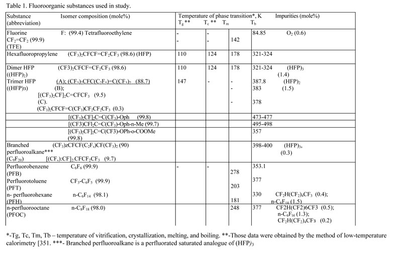
Table 3. Molecular products of TFE fluorination in organofluoric media (click the image to view PDF)

References
[2]. S. Rozen //Асc. Chem. Res. 1988. Vol. 21. P. 307.
[3]. Purrington S.T., Kagen B.S., PatricТ.В. // Chem. Rev. 1988. Vol. 86. P. 997
[4]. Rahimov A.I. Khimiya i tehnologiya ftororganicheskikh soedinenij. M.: Khimiya, 1986.
[5]. Lagow R. J., Margrave J. L. // Progr. Inorg. Chem. 1979. Vol. 26. P.162.
[6]. Florin R. E.// J. Fluor. Chem. 1973. Vol. 14. P.253.
[7]. Hayes L. J., Dixon D. D. // J. Fluor. Chem. 1977. Vol. 10. P.1.
[8]. Widdecke H. // Proc. 31 IUPAC Macromol. Symp. Merseburg. 1987. Microsymp. 2. 3. S. I. 140.
[9]. Muhametshin F.M . // Uspekhi khimii. 1980. T. 49. S.1260.
[10]. Scherer K.V., Ono T., Yamanouchi K. Patent US 4626608, (1986).
[11]. Haritonov A.P., Moskvin Yu.L., Kolpakov G.A. Patent RU 1754191 (1990).
[12]. Halasz S. P., Kluge F., Martini T. // Chem. Ber. 1973.Vol.106.P. 2950.
[13]. Zabolotskih V.F., Kochanov A.S., Tuinov A.V., Markin I.V. // Zhurnal Organicheskoj Khimii. 1994. T. 30. s.1219
[14]. Paleta O. // Uspekhi Khimii. 1971. T. 40. s. 777.
[15]. Panshin Yu.A., Malkevich S.G., Dunaevskaya Ts.S. Ftoroplasty. L.: Khimiya, Leningradskoe otdelenie. 1978. C.24.
[16]. Merritt R.F., Johnson F.A. // J. Org.Chem. 1966. Vol.31. P.1859.
[17]. Merritt R.F. // J. Am. Chem. Soc. 1967. Vol. 89. P. 609.
[18]. Bormstein J., Borden M.R., Nunes F.,Tarlin H. // J.Am. Chem. Soc. 1963.Vol.85. P. 1609.
[19]. Shellhamer D.F.,Conner R.J.,Richardson R.E.,Hesslay V.L. //J.Org.Chem.1984.Vol. 49. P.5015.
[20]. Sherer K. V., Ono T., Yamamouchi K., Fernandez R. E., Henderson P., Goldwhite H. // J. Amer. Chem. Soc. 1985. Vol. 107. P.718.
[21]. Scherer K.V. // J. Fluor. Chem. 1986. Vol. 33. P.298.
[22]. Allayarov S.R., Sumina I.V., Barkalov I.M., Bahmutov Yu.L., Asamov M.K. // Izv. VUZov. Khim. i Khimich. Tekhnol. 1986. T. 32. S. 26
[23]. A.E. Shilov. Khimicheskaya kinetika i tsepnye reaktsii. M.: Nauka, 1966.
[24]. Allayarov S.R., Barkalov I.M., Kim I.P. // J. Fluor. Chem. 1999. Vol.96. P.57.
[25].Fernandez R.E. Dissertation of degree Doctor of Philosophy (Chemistry).Southern Carolina. 1987.
[26].Henderson P.V. // Dissertation of degree Doctor of Philosophy (Chemistry). Southern Carolina. 1987.
[27]. Allayarov S.R. // Dis. dokt. khim. nauk. M., 1993.
[28]. Allayarov S.R. // Zhurnal organicheskoj khimii. 1994. T. 30. S. 1147.
[29]. Allayarov S.R., Bol'shakov A.I., Barkalov I.M. // Vysokomolek. Soed. 1987. T. A29. S. 364.
[30]. Allayarov S.R., Kim I.P., Barkalov I.M., Ivanova L.M., Il'in A.N. // Khimiya Vysokih Energij. 1993. T. 27. S. 22.
[31]. Allayarov S. R., Barkalov I. M., Kim I. P. // Mendeleev Comm. 1992. s. 139.
[32]. Scherer K.V., Fernandez R., Henderson P.B., Krusic P.I. // J. Fluor. Chem.1987. Vol. 35. P. 167.
[33]. Allayarov S.R., Konovalihin S.V., Gordon D.A., Chernysheva T.E., Barkalov I.M. // Khimiya vysokih energij. 2002. T. 36. s. 445.
[34]. Allayarov S.R., Mihajlov A.I. // Izvestiya Akademii Nauk. Seriya khimicheskaya. 2001. s. 1142.
[35]. Barkalov I.M., Kiryukhin D.P. // Int. Rev. Phys. Chim. 1994. Vol.13. P.337.
Fluorine Notes, 2010, 72, 1-2