Fluorine Notes, 2006, 49, 3-4
|
Implementing Methods for Contact of Fluorine and Graphite During Synthesis of Lowest Perfluoroalkanes G.G Shelopin, D.S. Pashkevich, D.A. Mukhortov, Petrov V.B. FSUE RSC "Applied Chemistry", St.Petersburg, Dobrolubov ave. 14 Introduction In this work we have studied the obtaining process of lowest perfluoroalkanes (tetrafluoromethane, hexafluoroethane, octafluoropropane, decafluorobutane) at high temperature interaction of graphite and fluorine in dynamic (non-stationary, mixed) layers of powders. Tetrafluoromethane, hexafluoroethane, octafluoropropane and decafluorobutane find their wide application in modern industry. They are used as ozone-friendly refrigerants, propellants, dielectrics, reagents for plasma-chemical etching etc., their world consumption reaches level of several tons per year [1]. That's why creating of competitive technologies for their production is an urgent task. Nowadays the compounds named above can be produced using different methods. Tetrafluoromethane is obtained out of elements in inverse wave of graphite filtration burning in fluorine with the use of stationary layer of graphite [2]. Hexafluoroethane can be obtained using catalytic fluorination of fluorochloroethanes by anhydrous hydrogen fluoride [3]. The raw materials for these processes is ozone-depleting and their production must be suspended. Besides that, there are some other disadvantages among them we can name large amount of anhydrous hydrogen fluoride waste products and necessity for regeneration and utilization of chrome-magnesium-fluoride catalyst, which is hazardous to environment. Octafluoropropane is produced out of hexafluoropropylene [4, 5] using cobalt trifluoride fluorination. During production of hexafluoropropylene they also use ozone-depleting raw materials, which application must be prohibited [1]. Besides that, technological processes applying cobalt trifluoride as fluorinating agent are noted by low productivity. Decafluorobutane can be obtained using electrochemical fluorination of tributylamine in the solution of anhydrous hydrogen fluoride [6]. However, this method is noted by low yield of target product and low productivity. At the same time it is known, that all named perfluorocarbones and also solid compound of fluorographite (CFx)n form at interaction of graphite and fluorine at high temperature:
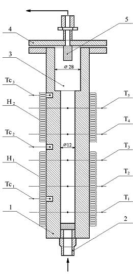
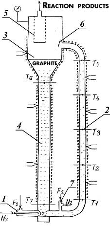
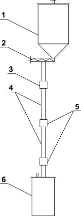
At commercial implementing of graphite fluorination in non-stationary layer several totally different synthesis methods for compounds named above can be replaced for one based on simple and cheap raw materials with effective rectifying separation system. Boiling points of tetrafluormethane, hexafluoroethane, octafluoropropane, decafluoropropane are -128, -78, -37, -2 oC respectively and at implementing into commercial production the segregation of reaction mixture into individual compounds using rectification is considered to be a task not so hard to execute. Effective tetrafluoromethane obtaining technology is commercially developed, and that's why creating a perfluoroalkanes' production using fluorination of carbon is appropriate only when compounds named above can be obtained during this synthesis at comparable quantities. The main purpose of this work is search for graphite fluorinating conditions at which we get perfluoroalkanes' mixture, in which hexafluoroethane, octafluoropropane and decafluorobutane are in comparable amounts. Interaction of fluorine and carbon is noted by high emission of heat": at obtaining of tetrafluoromethane thermal effect amounts to 932 KJ/mole [2], under adiabatic conditions the temperature of reaction products is about several hundred degrees. We need to withdraw heat from the zone of reaction and to maintain temperature at 1000 oC. there to increase yield of hexafluoroethane, octafluoropropane and decafluorobutane. In reacting scheme of gas-solid substance it can be done using dynamic layers of powder. Experimental Part High-quality milled synthetical graphite was used for laboratory tests (TU 48-20-54-84). Fluorinations of graphite were carried out using mixture of fluorine and nitrogen (or argon) in reactor with fluidizes bed [7], ascending gas-dust flow [8] and free falling layer of graphite [9]. The reactor containing fluidizes bed of graphite (fig.1) is a carbon steel thick-wall tube 1, its inner diameter is 12mm, external diam. equals to 45mm, height - 500mm. Porous insert made of extruded nickel powder is mounted into lower part of tube, through which fluorinating mixture is fed. There is an extension diam. 28mm in the upper part of the tube. The reactor is equipped with thermocouples and electrical heater. Fig. 1. Scheme of Reactor: 1 - Reactor's tube; 2 - Fitting for feeding fluorinating mix; 3 - Dust separation chamber; 4 - Reactor's cover; 5 - Filter; H1, H2 - Electrical heaters; T1, T2, T3, T4, T5 - central thermocouples; Tc1, Tc2, Tc3 - wall thermocouples. A laboratory unit (fig. 2) was created to study the fluorination process of graphite in gas-dust flow. The unit consists of ejector 1, lifting tube 2 (inner diam. 9mm, length 1,2m), separator 3 and falling tube 4 (diam. 20mm). Filter 5 and solid phase consumption sensor 6 are placed in reactor's separator. Tubes 2 and 4 are equipped by electrical heaters and central and wall thermocouples. Fig. 2. Scheme of Laboratory Reactor for Fluorination of Graphite in Vertical Ascending Gas-Dust Flow. 1 - Ejector; 2 - Lifting Tube; 3 - Separator; 4 - Falling Tube; 5 - Filter; 6 - Consumption Sensor; 7 - injector; T1-T7 - Central Thermocouples. Interaction of fluorine and graphite occurs in lifting tube mostly forming carbon polyfluoride at 530-580 oC, decomposition of carbon polyfluoride takes place in separator and falling tube at temperature about 600 oC. Laboratory reactor with freely falling layer of graphite (fig. 3) consists of the following elements: supply bunker filled with graphite diam.120 mm, volume 2100 cm3 1; dosing auger device 2; fluorine feeding module 3; reaction tubes diam. 12mm, length 300mm 4, modules for temperature and fluorine presence control in reaction zone 5, receiving bin diam. 120mm volume 2400 cm3 6. Temperature of supply hopper 1, reaction tubes 4 and receiving bin 6 is set and maintained by electrical heaters. Reaction tube is made of interchangeable pieces connected by control junctions to provide an option for changing contact time of fluorine and carbonic material.
Fig. 3. Scheme of "Falling" Layer Reactor. 1 - supply hopper; 2 - auger dosing device; 3 - fluorine fed in module; 4 - reaction tube; 5 - control unit; 6 - receiving bin. In free falling layer reactor the graphite powder is fed in using auger dosimeter into overhead part of vertical hollow tube, inside which the particles of graphite move under conditions of free falling. Fluorine is fed also into overhead part of this tube. At interaction of fluorine and graphite, which is in large excess, carbon polyfluoride is formed at total conversion of fluorine. Thermal decomposition of carbon polyfluoride is carried out in static layer of powder in the bottom part of reactor. Results At temperature about 600oC syhthesis of CF4, C2F6, C3F8, C4F10 goes according to two-stage scheme of "synthesis of solid carbon polyfluoride (CFx)n and thermal decomposition of (CFx)n". Composition of products of carbon polyfluoride thermal decomposition process depends on the presence of gaseous fluorine in the decomposition area. At that, the increasing of gaseous fluorine amount in decomposition area lowers longer carbonic chain fluorocarbones' share. That's why the spatial separating of fluorine and graphite interaction area with forming of carbon polyfluoride and thermal decomposition area of carbon polyfluoride provides the increasing of share of fluorocarbones with the carbon atoms number higher than 1 in the structure of gaseous reaction products. In table 1 we can see a composition of gaseous graphite and fluorine interaction products in the reactors of fluidizes bed, ascending gas-dust flow and free falling graphite layer. Table 1. Composition of Reaction Gas mixture at Fluorination of Graphite
When realization graphite fluorinating process in the fluidizes bed we can't achieve a spatial separating of carbon polyfluoride synthesis and thermal decomposition areas. Ascending gas-dust flow reactor also has a number of disadvantages that is necessity to use the inert gas (about 9 volumes per 1 fluorine volume) to create gas-dust flow, practical absence of opportunity to verify the graphite consumption, uncontrolled stripping of powder ejection, providing forming of gas-dust flow. When carrying out a process using a free falling layer reactor there is a number of advantages compare to reactors of fluidizes bed and gas-dust flow. Most important differences of using free falling graphite layer reactor are as follows: Separated and controlled feeding of reagents - dosing of graphite by auger dosimeter provides stable forming for gas-dust flow (falling layer) of targeted composition; separation of fluorine absorption area and carbon polyfluoride decomposition area; application of auger allows to decrease the use of inert gas and to simplify the target products isolating technology. Summary 1. Under laboratory conditions the perfluoroalkanes synthesis out of graphite and fluorine goes according to "carbon polyfluoride synthesis - its thermal decomposition" scheme. 2. Application of auger dosimeter allows providing stable forming of fluorine and graphite gas-dust flow in a wide range of components consumption alteration. It also allows providing and maintaining temperature modes for synthesis and thermal decomposition of carbon polyfluoride, which are close to optimal from the point of view of gaseous reaction products composition. 3. Applying of graphite falling layer reactor enables lowering of inert gas concentration in its mixture with fluorine compare to reactors of aerated layer and ascending gas-dust flow. References |
||||||||||||||||||||||||||||
1. Promyshlennye ftororganicheskie produkty: Sprav. izd./Maksimov B, N., Barabanov B G., Serushkin I. L. i dr, SPb: Khimiya, 1996. 544 s.
2. Pashkevich D. S., Muhortov D. A., Petrov V. B. i dr. Sposob polucheniya tetraftormetana // Patent RU 2117652. Zayavka na izobretenie 97105150. Prioritet 2.04.97.
3. Trukshin I. G., Vishnyakov V. M., Fedorova S. G., Issledovanie protsessa sinteza geksaftoretana iz hlorftoretanov / Tezisy dokladov 2 Mezhdunarodnoj konferentsii «Khimiya, tekhnologiya i primenenie ftorsoedinenij v promyshlennosti». SPb. 1997.
4. Asovich V. S., Alekseev Yu. I., Maruev A. V. i dr. Razrabotka tekhnologii polucheniya oktaftorpropana povyshennoj chistoty // Otchet o NIR «Ozonobezopasnye hladony». NPO GIPH, 203/90. SPb. 1990. 191 s.
5. Asovich V. S., Kornilov V. V., Kostyaev P. A. i dr. Ftorirovanie uglevodorodov vysshimi ftoridami kobal'ta, margantsa, tseriya / Tezisy dokladov 1 Mezhdunarodnoj konferentsii «Himiya, tekhnologiya i primenenie ftorsoedinenij v prom'shshennosti». SPb. 1994. C. 15.
6. Kaurova G.I., Nikiforov B.L., Krasil'nikov A.A, i dr, «Razrabotka kompleksnoj tekhnologii polucheniya perftortributilamina i perftorbutana metodom elektrohimicheskogo ftorirovaniya tributilamina» Tezisy dokladov na 3-ej Mezhdunarodnoj konferentsii "Khimiya, Tekhnologiya i Primenenie Ftorsoedinenij" (CTAF'2001), 6-9 june 2001g, Sankt-Peterburg, str. 155
7. Pashkevich D. S., Shelopin G.G., Muhortov D. A. i dr Sintez perftoralkanov pri vysokotemperaturnom vzaimodejstvii grafita so ftorom v psevdoozhizhennom sloe. «ZhPKh», 2004, t.77, s. 1865-1871
8. Shelopin G.G., Pashkevich D. S., Muhortov D. A. i dr. Sintez perftoralkanov ftorirovaniem grafita elementnym ftorom v vertikal'nom voskhodyashchem gazopylevom potoke. «ZhPKh», 2006, t.79, s. 950-953
9. Shelopin G.G., Pashkevich D. S., Muhortov D. A. i dr. Sintez perftoralkanov ftorirovaniem grafita elementnym ftorom v reaktore s padayushchim sloem grafita.«ZhPKh», 2006, t.79, s.1040-1042
Fluorine Notes, 2006, 49, 3-4